It’d be a real stretch to say I needed to automate the blinds in my apartment, but it was fun, and I’m loving the result. Blinds open automatically at sunrise and close at sundown. It’s nice to wake up to the sun!

I designed most of this setup myself, and wanted to share how I approached it. There was a lot of prior art (a particular shoutout to The Hookup’s Guide), but nothing that worked the way I was wanting. Guides I ran across either mounted a motor inside of a 2″ track (mine are 1″), or were for pull-cord style blinds.
I wanted a motor mounted on the outside of the track to drive the existing worm gear. I rent and don’t want to be kicking myself too hard when I move out. These are super easy to (un-)install.
There are few parts I’ll cover in this post:
- The 3D-printed mount design w/ assembly instructions
- The driver circuit PCB
- Driver firmware (esphome w/ cover component) + Integration with HomeAssistant
- Wiring tips
Bill of Materials
Before going into any detail, here’s a bill of materials (links may contain affiliate codes). If you’re into tinkering, you’ll probably have most of these parts already.
Driver
- Wemos D1 Mini ESP8266 dev board
- A4988 unipolar stepper driver
- 28BYJ stepper motor (important: converted to bipolar, see below)
- 1000 µF electrolytic capacitor
- LM2596 DC/DC buck converter
- Barrel jack
- 2A 12V power supply
- 4 Pin screw terminal
- Driver circuit PCB (Available on OSH Park). Gerber files on Github.
Mount
- A 3D printer
- eSun White PETG
- M3 screws, etc. for assembly (this kit has all but the M3*30 screws):
- 2x M3*30
- 3x M3*20
- 5x M3 nuts
- 6x M3 washers
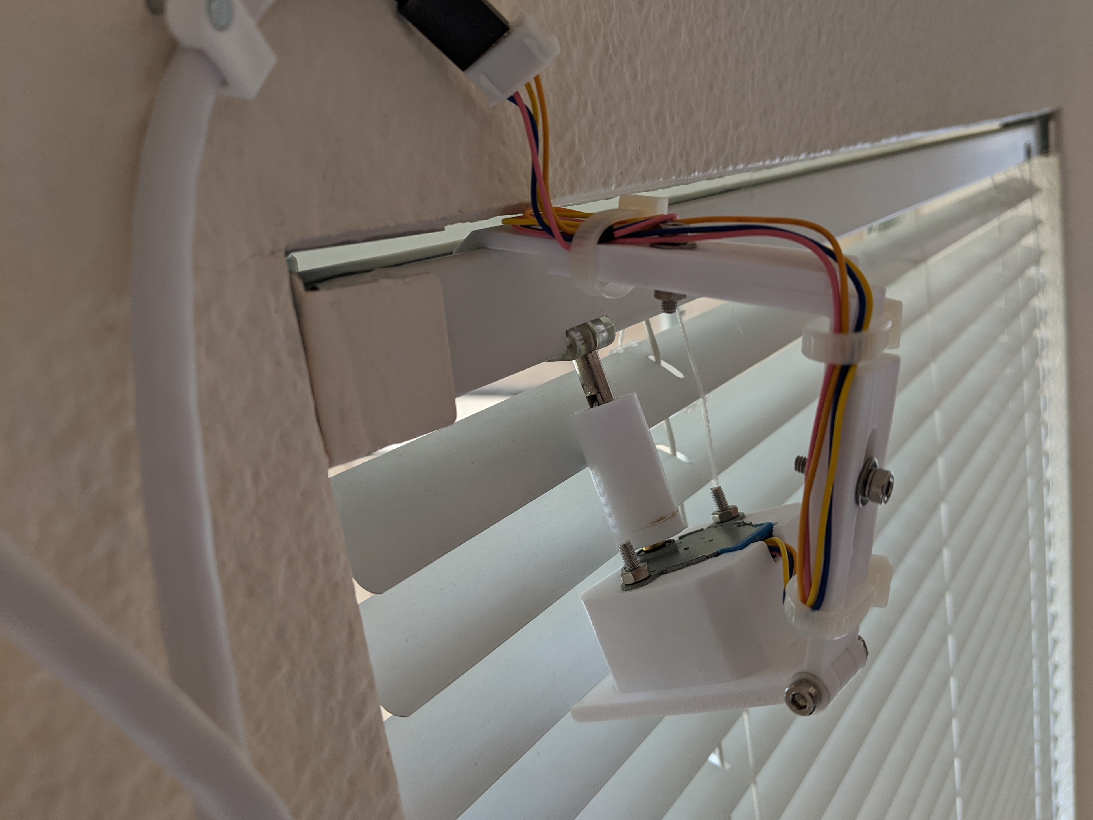
3D-Printed Mount
The STLs are available on Thingiverse and PrusaPrinters. PrusaPrinters has gcode for the mounting arm, which requires support in some strategic locations.
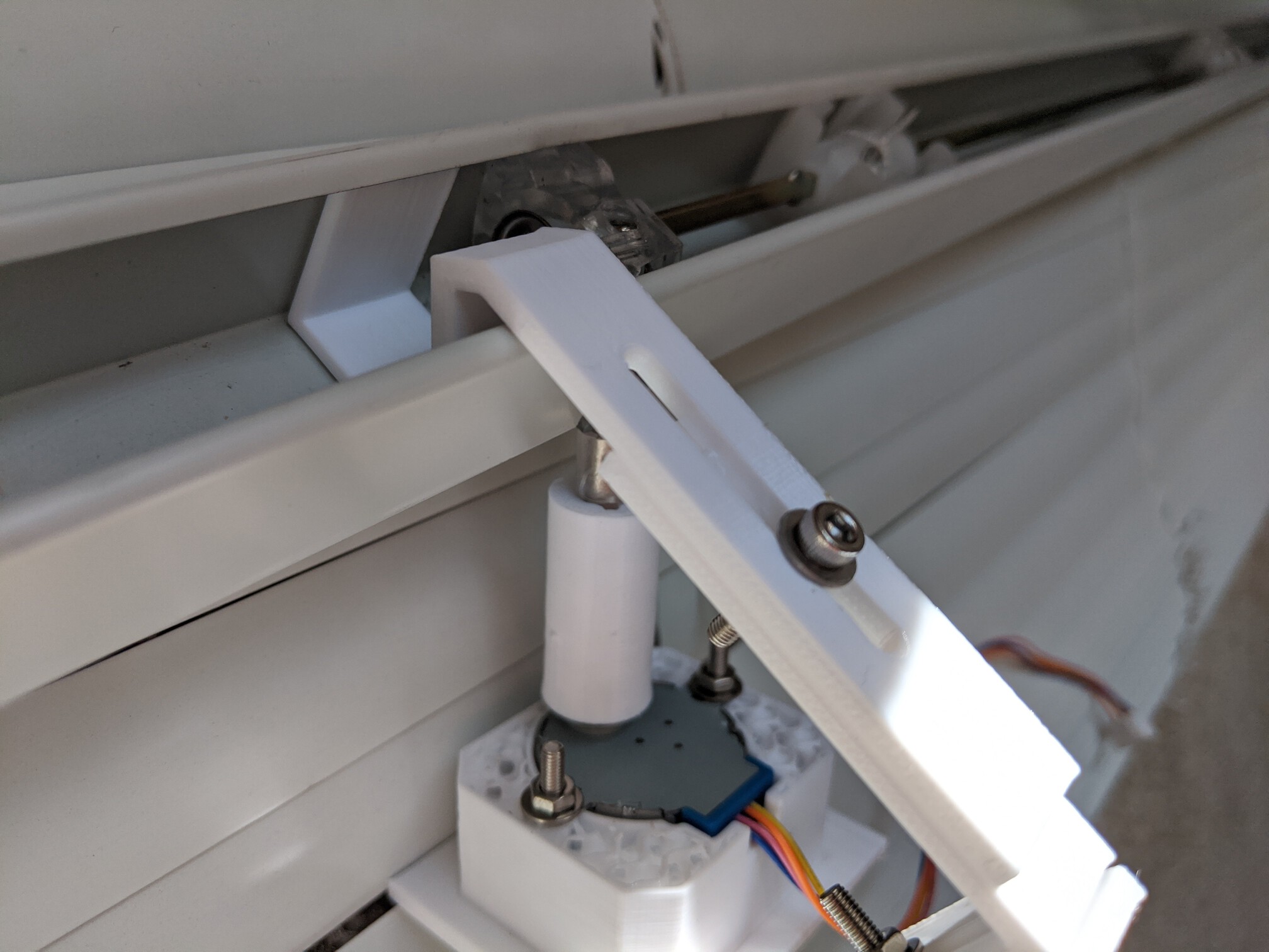
The mount’s design is simple — it slides into the track and holds the motor in place. Angles and lengths are adjustable so that the motor can be moved into the appropriate position. It’s held together with some M3 screws.
The only piece of this that is not one-size-fits-all is the motor adapter. It connects the shaft of the stepper motor and the worm gear driver. While the 28BYJ end probably always looks the same, I had three different worm driver shafts across my apartment.
Assembly should be pretty self-evident. Let me know if not and I can elaborate.
Convert 28BYJ stepper to bipolar
28BYJ motors are unipolar steppers. In order to use them with the A4988 driver (which supports a higher supply voltage), they must be converted to bipolar. Fortunately, this is pretty simple. Just crack open the blue casing on the side and cut the center PCB trace. I used a small file to do this, but an X-Acto knife or small screwdriver would work just as well.
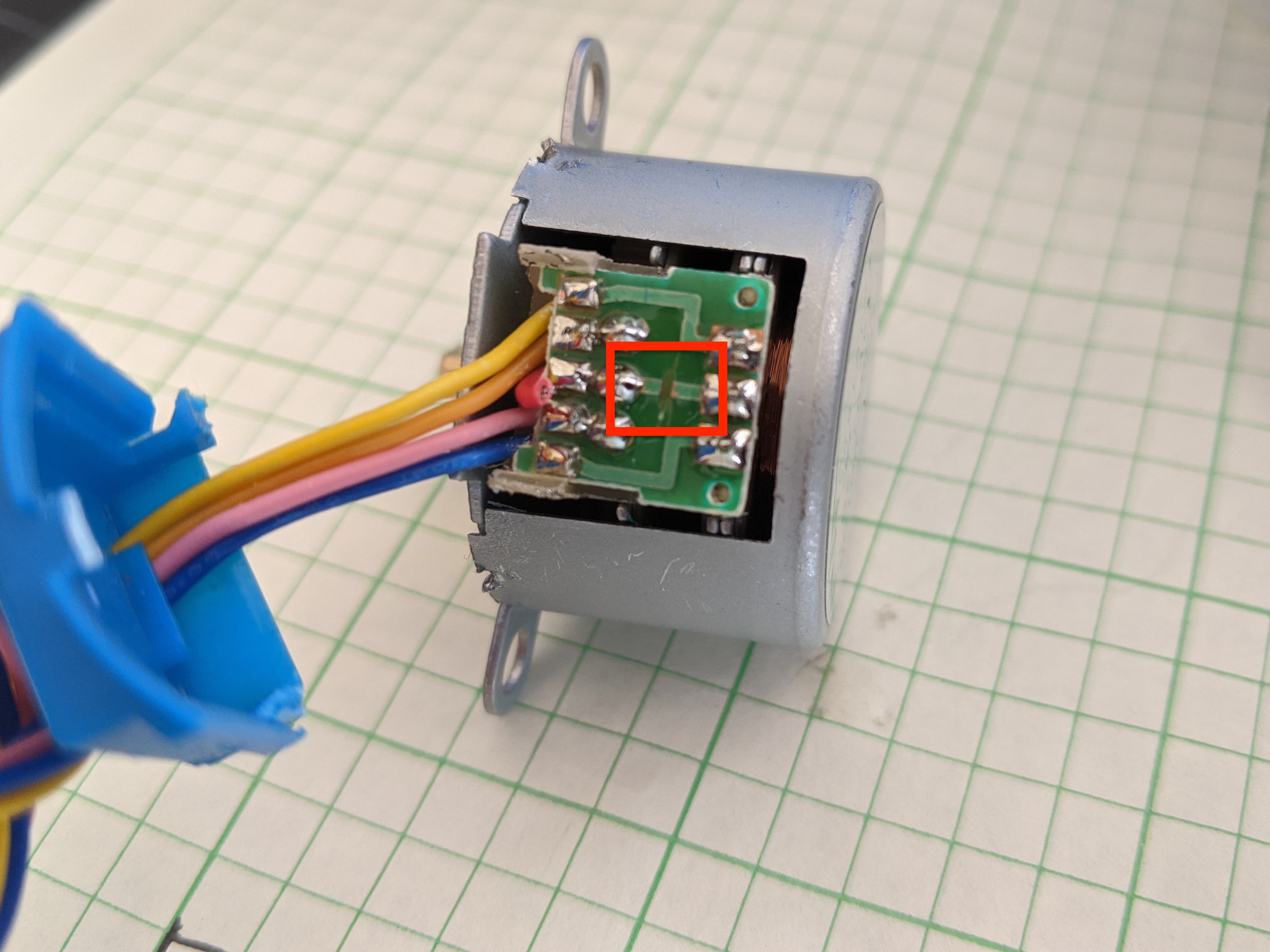
You’ll probably need to break some of the plastic legs on the casing to get it open, but it closes back up well enough without them. I also snipped the lead wire going to this trace to avoid future confusion.
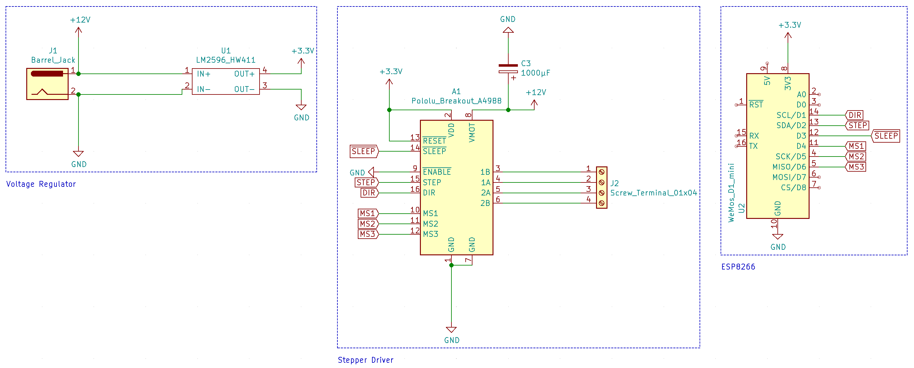
Driver Board
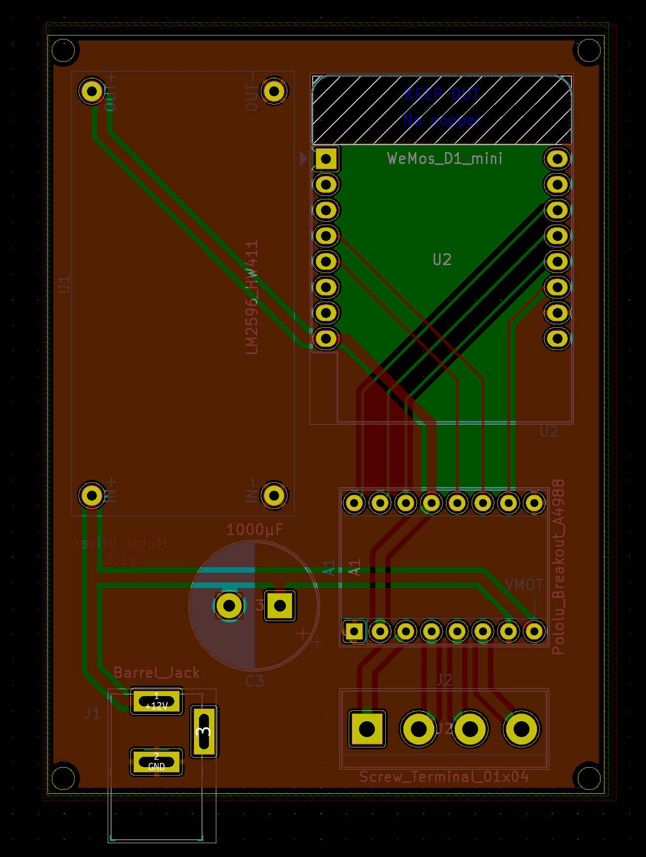
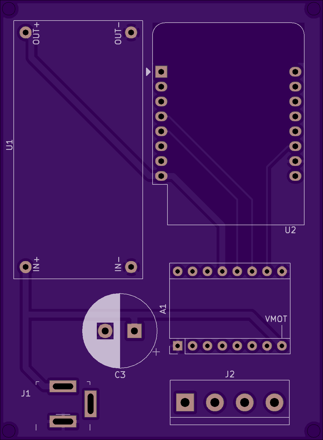
The schematic for this board is pretty simple and has three main components: an ESP8266, an A4988 stepper driver, and a voltage regulator (I used an LM2596-based board).
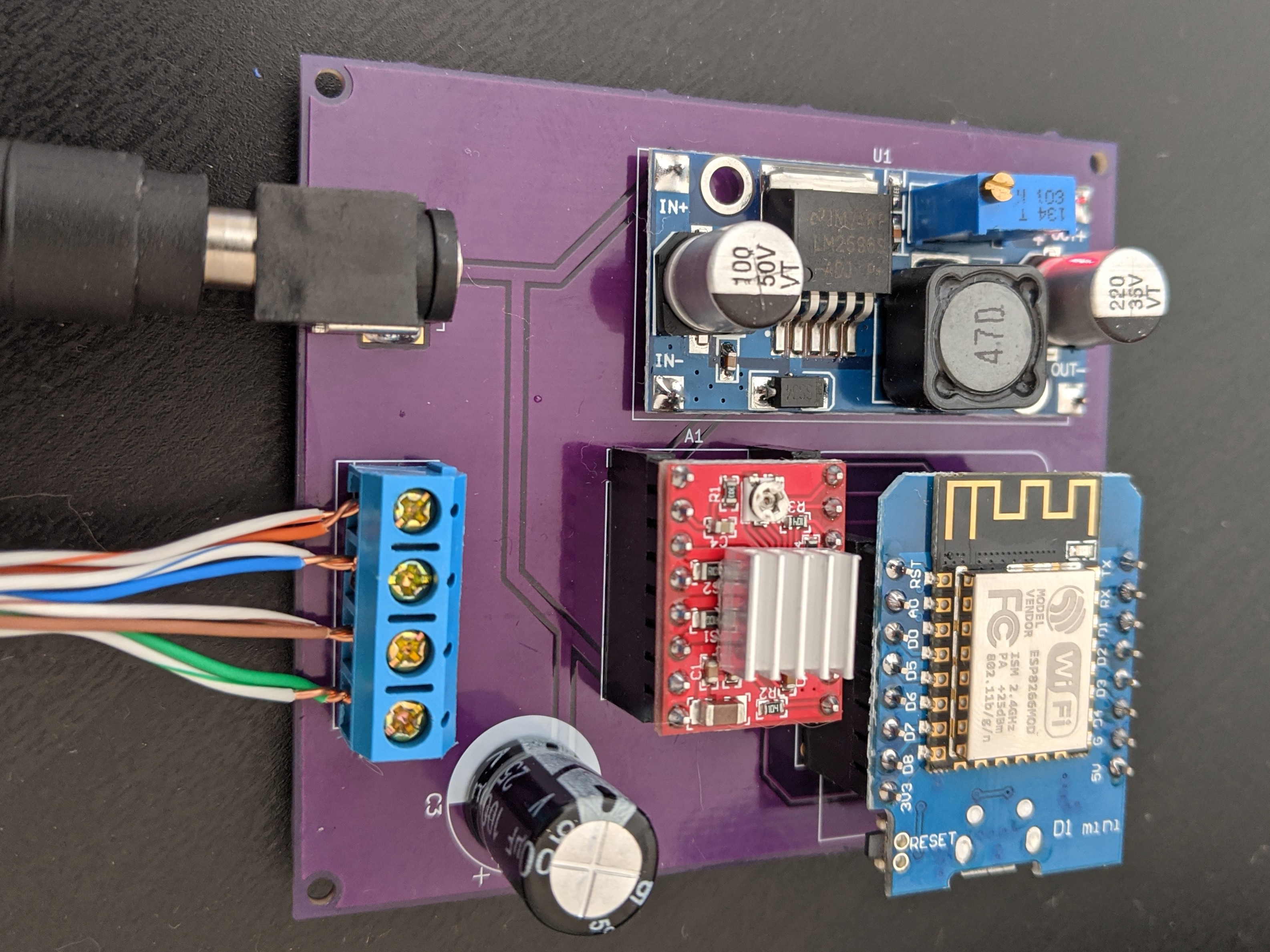
This worked just fine on a perfboard, but because I wanted several of these, I used this project as an excuse to familiarize myself with Kicad and get some PCBs made from OSH Park (project available here, all kicad+gerber files are on Github). I was very happy with the result:
Assembly Instructions
- Make sure to adjust the output voltage of the LM2596 to 3.3v! You’ll fry the D1 Mini if you don’t do this.
- Soldering components should be pretty straightforward as they’re all through-hole.
- I would recommend using headers for the A4988 and Wemos D1 Mini in case either gets damaged.
- Most D1 Mini kits come with two sets of 8-pin headers. Since the A4988 is a 2×8 pin board as well, this works out perfectly.
Driver Firmware
For this project, I wanted to try out ESPHome. I’ve written my own firmware for almost all of my EPS8266 projects. It was fun while it lasted, but the thought of gluing MQTT libraries to crappy C++ code didn’t sound exciting this time.
ESPHome’s Template Cover component does the trick quite nicely. I’ve put the YAML definition on Github. Flashing the D1 Mini with generated firmware is pretty simple. I used this command:
|
1 2 |
esphome office_blinds.yaml compile && \ esptool.py -b 460800 write_flash 0x0000 office_blinds/.pioenvs/office_blinds/firmware.bin |
(obviously you’ll need to have esphome and esptool installed).
You’ll also need a secrets.yaml that contains your wifi credentials and a setup password:
|
1 2 3 |
wifi_ssid: "your wifi network name" wifi_password: "your wifi password" fallback_ap_password: "a random password" |
The meat of the definition is in the template .blinds.yaml, including pin mappings from the ESP8266 and the A4988. If you chose pins different from those shown in the schematic above, make sure to correct them.
Parameters that are specific to a particular installation are substituted. In addition to names, you may also want to adjust the target parameter in the definition. This controls how many turns the motor completes when transitioning from one step to another. You can also negate it if you need to invert the direction (although you can accomplish this by reversing wiring as well).
The stepper position and cover state should be persisted across reboots.
HomeAssistant Integration
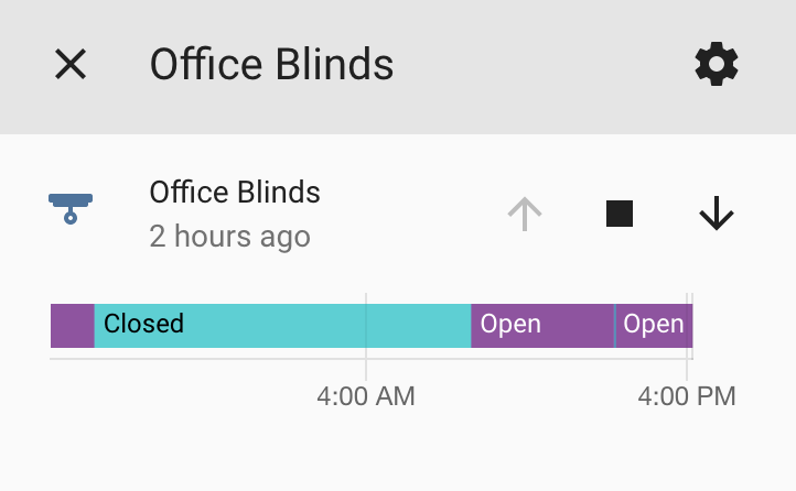
ESPHome works really seamlessly with HomeAssistant. Just add an ESPHome integration (Configuration > Integrations > + > ESPHome) using the hostname or IP of the ESP8266 (if you’re having trouble finding this, it’ll appear in serial logs after flashing the firmware).
This adds the cover component and allows you to control the blinds:
To address a situation where I need to calibrate the position, I have these scripts:
|
1 2 3 4 5 6 7 8 |
office_blinds_set_open: alias: Office Blinds - Set Open Position sequence: - service: esphome.office_blinds_set_open_position office_blinds_set_closed: alias: Office Blinds - Set Closed Position sequence: - service: esphome.office_blinds_set_closed_position |
Calling them will tell ESPHome to consider its current position as either open or closed. In combination with the up/down/stop action buttons, this will allow you to get your blinds into the desired state.
Wiring Tips
You can use any sufficiently large four-wire cable to connect the driver to the motor. Ethernet cable works really well. I used one twisted pair for each lead. Stranded ethernet + crimped header would be best, but I only had solid core ethernet, so I soldered some headers on and called it a day.
Here are some pictures that hopefully help as a wire guide:
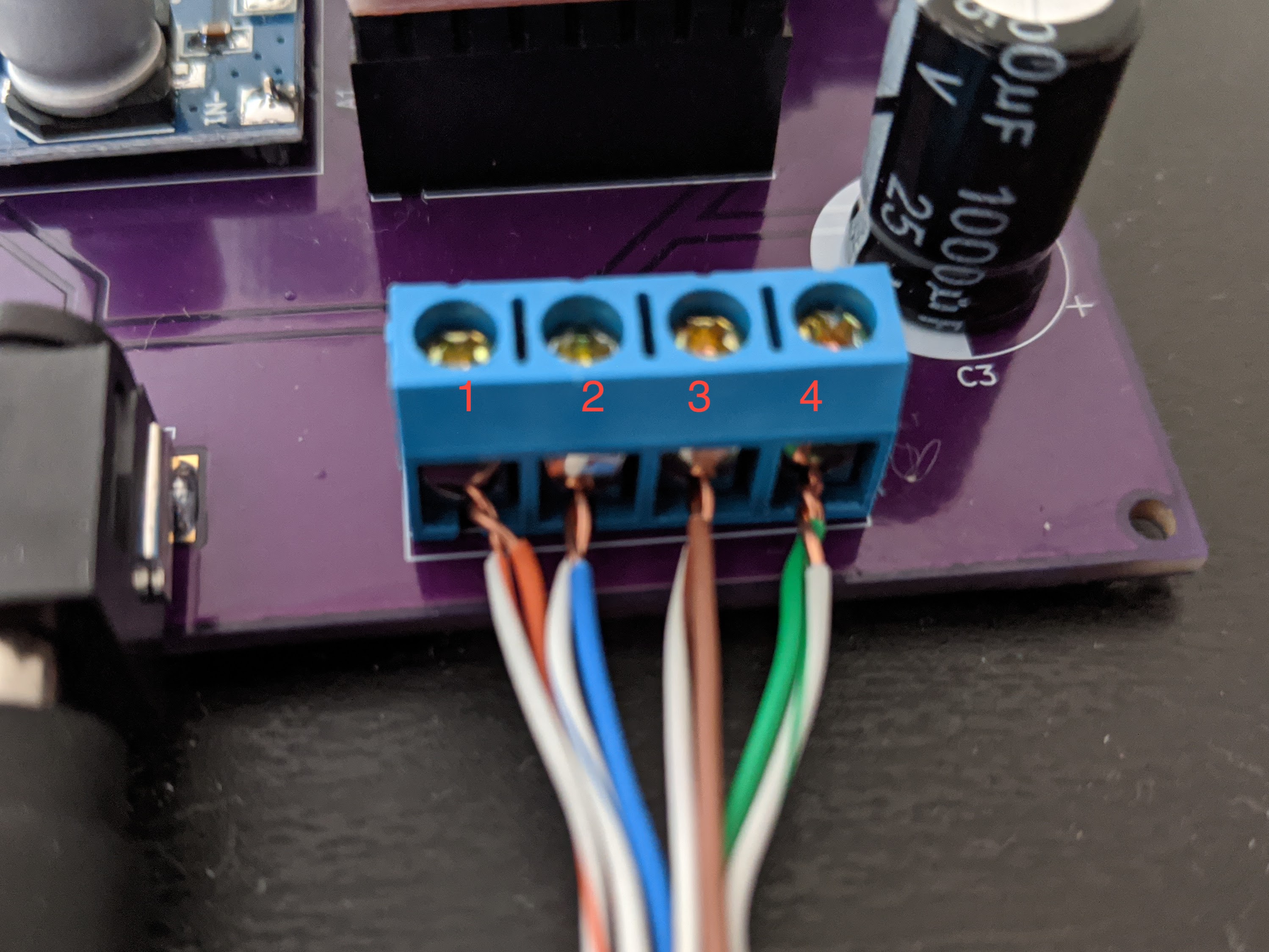
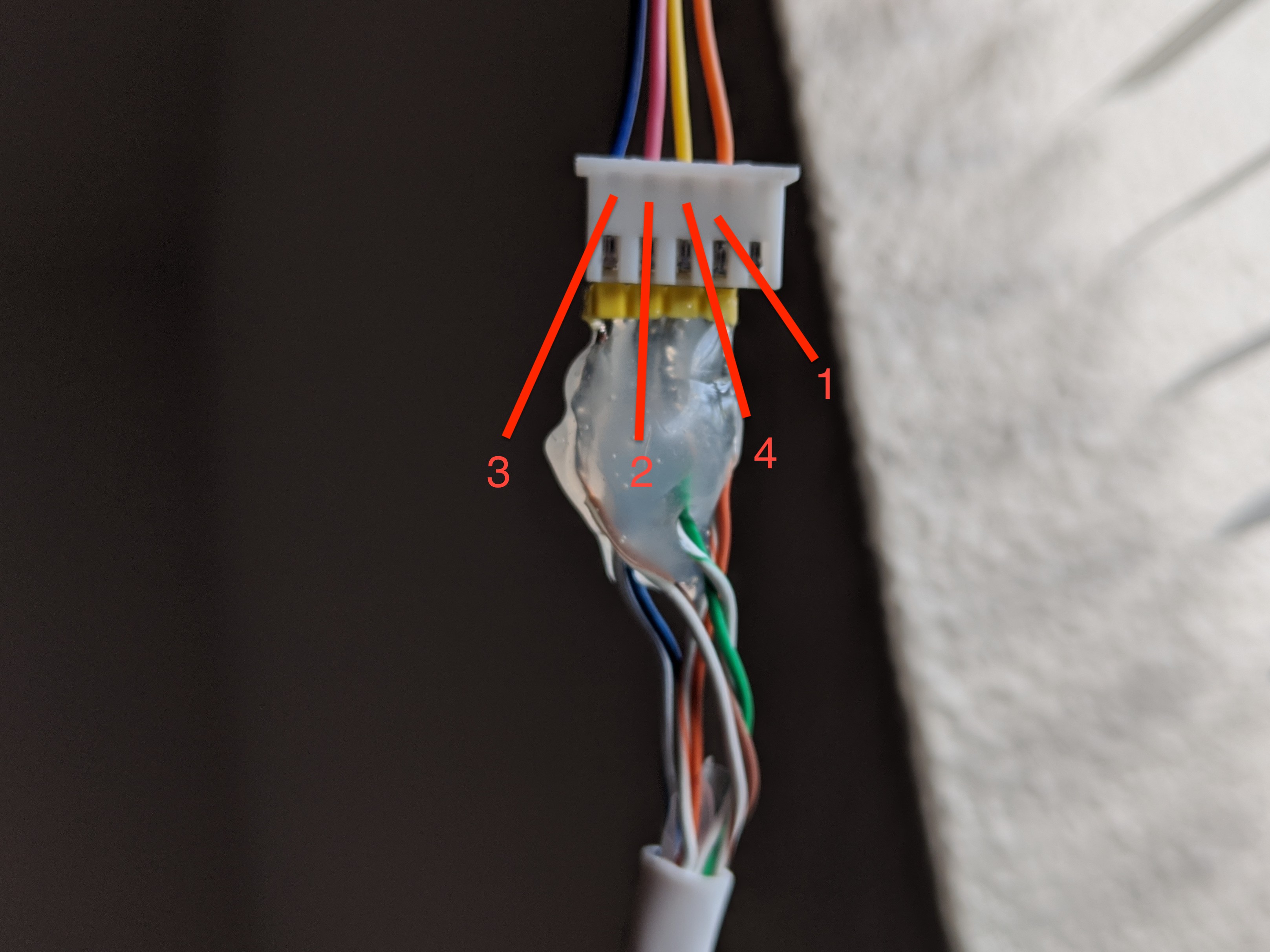
Note that you can reverse the order in which they’re connected (1/2/3/4 -> 1/4/2/3) to invert the directions the stepper turns for open/close.
Updates
September 29, 2022
- Significant updates to the ESPHome yaml definitions
- Stepper position persisted across reboots
- Adds pin definitions for MS1/MS2/MS3 on A4988 used to control step granularity. These need to be pulled LOW during operation.
- By default D4 is used for MS1. D4 is also tied to the internal LED on the D1 Mini. I have this pin kept HIGH during idle so the LED stays off. It’s pulled LOW while the stepper is running, which has the nice side-effect of the LED lighting up while the motor is (or should be) running.
Links
- Driver board kicad project files (schema/pcb)
- Gerber file archives (for use with jlcpcb, etc.)
- Order driver board from OSH Park
- ESPHome definition for firmware
Hello I am trying to use you code and PCB to drive a Nema 17 stepper motor. All i want is the sett a start and a stop. WHY is this so hard to understand ESPhome.
I can get the motor to spin like 1mm that is alla:/
src/main.cpp: In function ‘void setup()’:
src/main.cpp:581:76: error: invalid conversion from ‘esphome::globals::RestoringGlobalsComponent*’ to ‘int’ [-fpermissive]
581 | end_position = new globals::RestoringGlobalsComponent({end_position});
| ^
| |
| esphome::globals::RestoringGlobalsComponent*
In file included from src/esphome.h:24,
from src/main.cpp:3:
src/esphome/components/globals/globals_component.h:31:40: note: initializing argument 1 of ‘esphome::globals::RestoringGlobalsComponent::RestoringGlobalsComponent(T) [with T = int]’
31 | explicit RestoringGlobalsComponent(T initial_value) : value_(initial_value) {}
| ~~^~~~~~~~~~~~~
*** [/data/garage/.pioenvs/garage/src/main.cpp.o] Error 1
========================= [FAILED] Took 16.43 seconds =========================
I get this:/ and dont understand what is wrong
Ich bin neu im Forum und möchte mich kurz vorstellen.
Ich habe einen grossen Garten und erfreue mich jeden Augenblick darin. Zudem grilliere ich leidenschaftlich und habe so immer gute Essen vom Holzkohlegrill und kühle Getränke.
Ordered 3 pcb with all the parts.. I wasnt able to make a single motor spin 🙁 I’ll try to change the a4988 driver
i did not get it to work… but i have study the PCB, havet test it out yet. But i cant find any Ground to the D1 mini. Or am i missing somthing?
Sorry for the giga late reply here, totally missed this until now. You definitely need to use an A4988 or at least something with the same footprint and pinout.
@Daniel, the D1 mini is connected to the ground plane on the reverse side of the board.
I hope this will make my life better, i order 5 PCB. i am not good at coding at all, dont even understand it.
but can i sett a stop on the motor?
and can i sett the speed?
You are the man! I recently decided to do this exact project except for using this stepper motor housing to pull the blind cords.
Man I cant thank you enough for laying out the ESPHome yaml and everything! Just ordered the parts I dont have laying around and cant believe I’m going to be able to automate my blinds for less than $10/ea.
Thanks again mate.
forgot to include the link to thingiverse stepper motor housing
Do you guys know if it is possible to control two Stepper Motors using two A4988 drivers (one for each motor) on the same D1 Mini?
Can you please explain the need for the capacitor between the 12V supply and the stepper motor controller? I’m new to this and curious. Will this work without the capacitor?
I believe it’s to protect the A4988 from voltage spikes that can occur when it’s powering up, but I just put it there because the datasheet told me to if I’m being honest :).
There’s some documentation on the Pololu website if you’re curious to learn more:
https://www.pololu.com/product/1182
Actually, nevermind. I realized that while I was tweaking the yaml to invert the pin as I described, it was sitting there heating up because the stepper had not actually been disabled or put to sleep. I let it cool off and now when it operates it’s still cool to the touch after a few cycles.
Hope this helps anyone else!
Thanks for this Chris. I’ve had MG995 servos controlling most of my blinds for a while now, but wanted to move to a stepper motor for more torque on a larger blind that the servo just never did well with. I first watched Rob’s (The Hook Up) Youtube video and then found your post here after wanting to go the ESPHome route as well. I hooked it up the way he did, using the Enable pin instead of the Sleep pin just so that there’s no current going to the motor when it’s not turning. I just had to invert the sleep pin in my yaml as follows:
sleep_pin: number: D3 inverted: True
Have you noticed that the motor gets almost too hot to the touch when it operates? I know Rob mentioned that and also said that he didn’t change the current limiting potentiometer on the stepper driver. Did you? I’m all about a lot of torque, but I don’t want my house to burn down in the process.
Rob’s videos are great — glad I could provide a modicum of supplement. 🙂
My understanding is that both sleep and enable disengage the stepper. I believe sleep puts the actual driver chip to sleep, while enable just turns off power to the motor. The datasheet confirms this:
In other words, “sleep” is actually more aggressive than “enable.”
Like you noticed in your followup, I don’t think the stepper runs for long enough for heat to be a problem. My understanding is that the driver will burn out before the motor does.
Hello! It’s not clear why and where the MS1-MS2-MS3 connected on the ESP. That’s not in the ESPhome code… Do I need to connect it? What are they doing?
Those are used to control the microstep resolution. It’s okay to leave them floating (and I don’t think that ESPhome supports them anyway).